Radar Errors, Clutter and False Echoes
RadarWhy radar never shows the world exactly as it is: range and bearing errors, sensor-induced errors, blind and shadow sectors, sea and rain clutter, and the four families of false echoes — and how a watchkeeper recognises and manages each one.
Last reviewed 1 Nov 2026 · From a professional captain's years of study notes · Organised with AI and checked against current regulations · How we write
On this page (12)
Why radar information is never exact
In short: radar measures only range and bearing. Everything else (CPA, TCPA, vectors) is derived, so every error spreads.
Read first: Radar Rules and Performance Standards. This is the second topic of the Radar area.
Marine radar measures two things: the time delay of a returning pulse (range) and the direction of the antenna when the echo returns (bearing). Every other figure on the display — CPA, TCPA, target vectors, true course and speed — is derived from those two measurements plus data from other sensors. An error in any input propagates into everything calculated from it.
This is why COLREG Rule 7(c) warns that assumptions shall not be made on the basis of scanty information, especially scanty radar information. Knowing where the errors come from is what separates using a radar from trusting it blindly.
Range errors
In short: range is the accurate measurement — within 30 m or 1 % of the scale (IMO MSC.192(79)). Measure on the front edge of the echo.
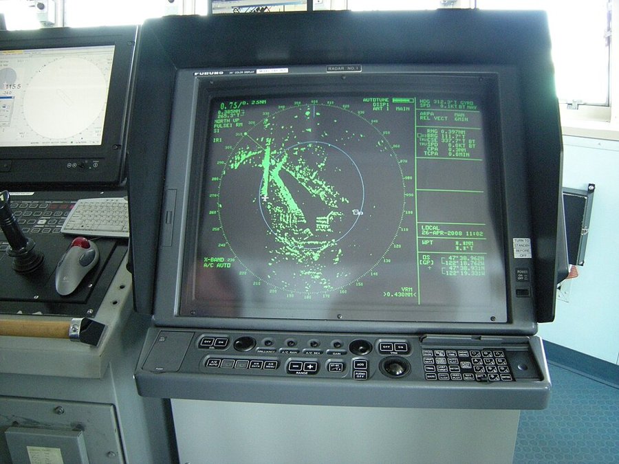
Range is the more accurate of the two radar measurements. IMO performance standards (MSC.192(79)) require range accuracy within 30 m or 1 % of the range scale in use, whichever is greater. The main error sources:
- Time synchronisation error — the instant the pulse leaves the antenna does not coincide exactly with “0 NM” on the display. Check: on minimum range, a straight linear target (jetty, seawall) that displays curved reveals a trigger-delay error.
- CCRP offset error — the consistent common reference point is set at installation and must stay correct.
- Measurement instrument error — the VRM and fixed range rings have their own tolerances; on older sets, calibrate the VRM against the range rings every voyage or every month, whichever is shorter.
- Pixel/spot size — significant on long range scales, where one pixel represents a large distance.
- Pulse length — the echo trailer degrades the trailing edge; measure ranges on the front edge of the echo.
Bearing errors
In short: bearings are the weak measurement — small errors add up to about ±2.5°. Prefer ranges when you fix.
Bearings are the weak measurement. The standard allows a maximum system error of 1° — but that figure covers the angle measurement alone. Add a heading-marker misalignment of up to ±1° and a gyro error of ±0.5°, and a displayed bearing can be ±2.5° off without any single component breaching its standard.
Contributing factors:
- Horizontal beamwidth (HBW) — the dominant factor. The beam has width, so every echo is widened by half a beamwidth on each side. Bearing the centre of a point echo needs no correction; bearing the left edge requires adding half the beamwidth, the right edge subtracting it.
- Heading marker and THD errors — affect relative and true bearings alike. The heading marker must be aligned within 1° of the fore-and-aft line and realigned as soon as found substantially inaccurate.
- Bearing synchronisation, centring and pixel errors — each small, all additive.
- Yaw — ship’s yaw at the moment of reading hurts bearings far more than surge or sway hurt ranges.
Practical consequence: prefer ranges over bearings when fixing position, and in clear weather pair a visual bearing with a radar range for the best two-LOP fix.
Sensor-induced errors
In short: a gyro, log or AIS error goes straight into every target’s true course, speed, CPA and TCPA.
The radar picture is only as good as the sensors feeding it:
- Gyro/THD error corrupts true bearings (relative bearings are unaffected) and with them every target’s displayed true course, speed and vector — exactly the data used for collision-avoidance judgement.
- Own-speed error (SDME/log) corrupts target true data the same way. Use speed through the water for collision avoidance and SOG for navigation: a ground-stabilised picture in a current distorts target aspect and can mislead anticollision decisions.
- AIS-reported data carries its own faults: GNSS accuracy uncertainty, no integrity indication (you cannot verify the other ship’s sensors), dynamic-data update intervals stretching from 2 s to 3 min, and improper static settings — all feeding directly into AIS-derived CPA/TCPA.
Blind and shadow sectors
In short: blind = total blockage, shadow = partial. Both change with the loading condition.
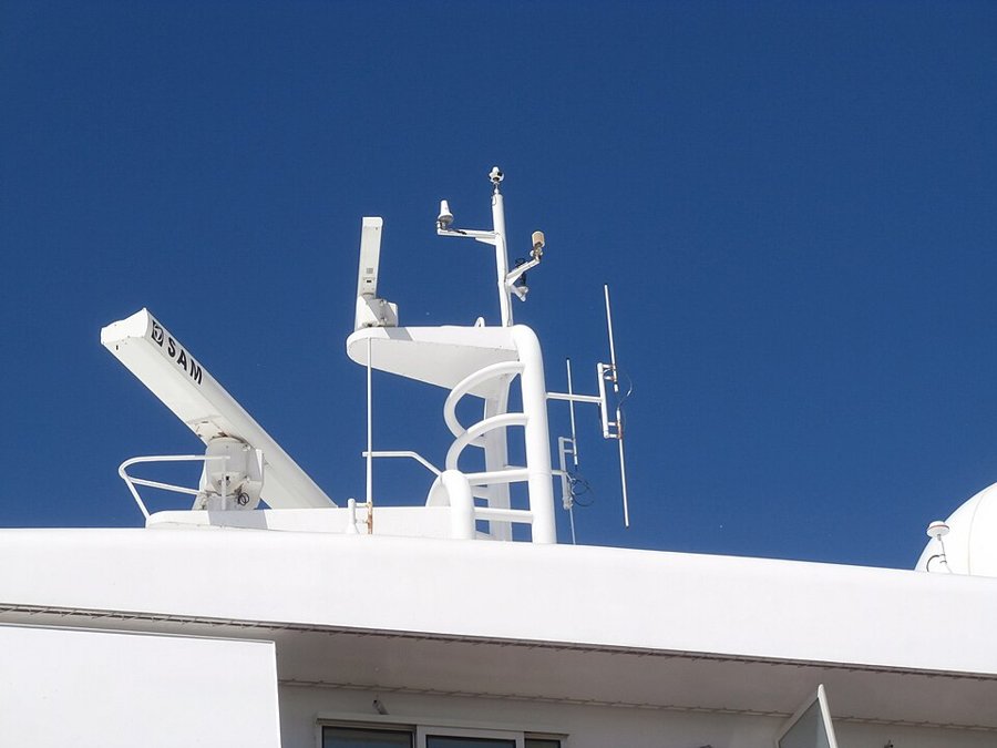
Masts, funnels, cranes and deck cargo block the beam:
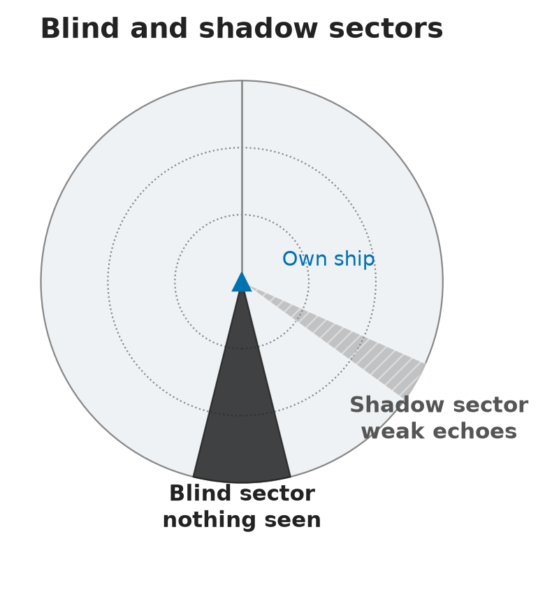
- A blind sector is a total blockage — no detection at all behind the obstruction.
- A shadow sector is a partial blockage — reduced or intermittent detection. The distinction is the degree of blockage, not its permanence.
Blind sectors change with loading condition (container stacks are the classic case): re-assess after every loading and inform the watch. Antenna height is a trade-off — higher means longer detection range and smaller blind sectors, but more sea clutter and a larger minimum range.
Sea clutter
In short: wave returns hide small targets close by, worst to windward. Set Sea/STC so a little speckle remains.
Returns from wave crests, worst at short range and fading with distance — typically out to 3–6 NM, up to 8–10 NM in rough seas. Stronger to windward, weaker to leeward. X-band (3 cm) suffers more than S-band (10 cm); a higher antenna and wider pulse make it worse.
The danger is what clutter hides: small close-range targets — buoys, small craft, a man overboard. The Sea/STC control reduces receiver gain at close range; over-suppression deletes weak genuine echoes along with the clutter. Correct setting leaves a slight residue of clutter speckle on the screen.
Rain clutter
In short: rain returns are fluffy with no edge, and X-band suffers more than S-band. Use FTC with care.
Precipitation returns appear as fluffy bright specks with no defined edge, strength proportional to rainfall; a tropical rainstorm can compromise detection seriously. X-band is attenuated far more than S-band — the longer wavelength wins in rain. The FTC (rain) control differentiates the echo edges; the same over-suppression caution applies.
False echoes
In short: indirect, multiple, side-lobe and second-trace echoes, plus power cables and aircraft. Treat a suspected false echo as real until proven false.
Four classic families, plus two special cases. The governing rule for all of them: treat a suspected false echo as real until proven false.
Indirect echoes
Energy deflected by an obstruction — on board (mast, funnel, container stacks, cranes) or external (a large vessel, buildings, bridges). The false echo appears on the bearing of the obstruction at roughly the true target’s range. It is weaker, distorted, and moves unnaturally. Reflections off the aft faces of container stacks can occur without any blind or shadow sector — and change with every re-stow. A bridge over a waterway can paint a false “ship” beyond the bridge that mirrors your every manoeuvre. Identify by altering course and watching the echo’s behaviour.
Multiple echoes
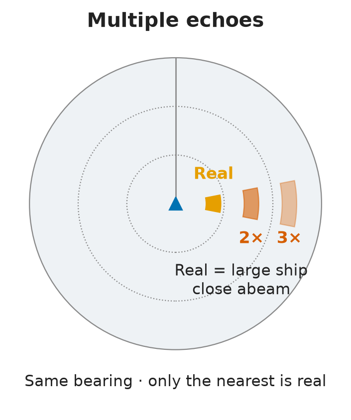
The pulse bounces repeatedly between own ship and a large close target (typically a big vessel abeam): several echoes on the same bearing at exact multiples of the true range, weaker outward, all moving with the real echo. Only the nearest is real. Reduce gain or use FTC to clean them up.
Side-lobe echoes
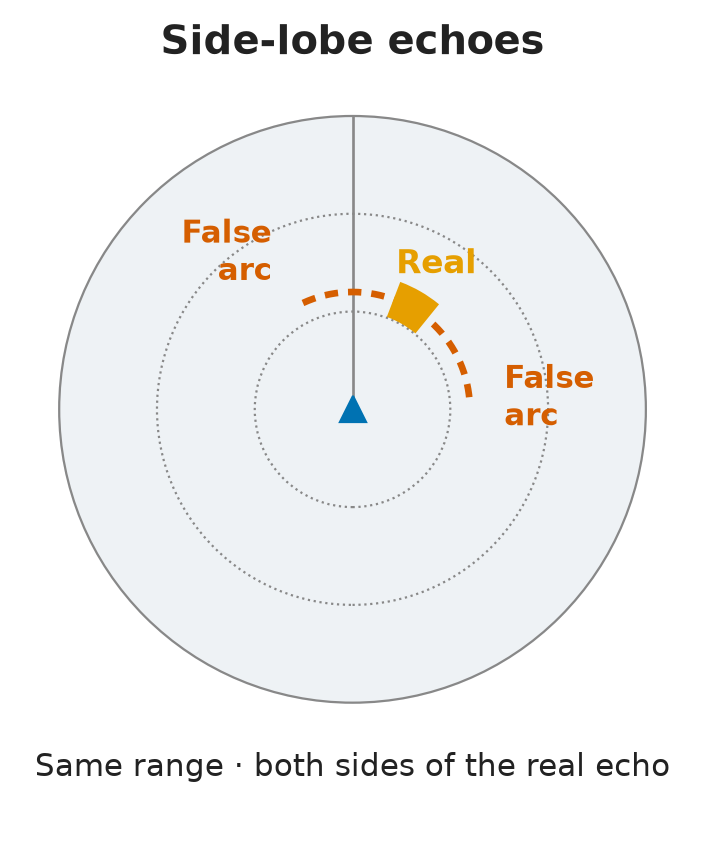
Close strong targets return energy through the antenna’s side lobes: arcs at the same range on both sides of the real echo. Worse with a small antenna or a dirty/damaged antenna window. Suppress with gain/STC/FTC — and keep the radome clean.
Second-trace echoes
Under super-refraction, an echo from a very distant target returns after the next pulse has been transmitted and is displayed at a false short range on the correct bearing, often distorted (a straight coastline becomes a “V”). Changing range scale changes the PRF and makes the echo jump or vanish — the diagnostic test. Modern radars jitter the PRF to break second-trace returns up.
Special cases
- Overhead power cables return a single point echo only when the beam is perpendicular to the cable — it looks like a vessel on a constant collision course whatever you do. Expect them on charted cable crossings; many cables carry radar reflectors.
- Low-flying aircraft paint a fast, jumping echo; if acquired by target tracking, a lost-target alarm follows shortly.
Watchkeeping checklist
In short: five habits that stop radar errors from fooling you.
- Measure ranges on the front edge; bearings on the centre of the echo.
- Keep gain slightly “dirty”: a speckle-free screen means weak echoes have been suppressed too.
- Know your blind/shadow sectors for the current loading condition.
- Cross-check radar information with an independent source — never verify GNSS with another GNSS-based system.
- Log unexplained echo behaviour; alter course to test a suspected false echo.
⚡ Flashcards
Test yourself, one card at a timeQ1Which two things does a radar actually measure?
AnswerRange (time delay of the echo) and bearing (antenna direction). CPA, TCPA and vectors are derived — COLREG Rule 7(c): no assumptions on scanty radar information.
Q2What range accuracy does IMO require?
Answer30 m or 1 % of the range scale in use, whichever is greater (IMO MSC.192(79)). Measure on the front edge of the echo.
Common trapMeasuring on the trailing edge — the pulse length smears it.
Q3How far off can a displayed bearing be?
AnswerAbout ±2.5°: 1° system error + up to ±1° heading marker + ±0.5° gyro, each within its own standard.
Common trapThinking the ‘1° maximum’ covers the whole chain.
Q4Which speed do you feed the radar for collision avoidance?
AnswerSpeed through the water (sea-stabilised picture). SOG is for navigation.
Common trapA ground-stabilised picture in a current distorts target aspect.
Q5Blind sector or shadow sector — what is the difference?
AnswerBlind = total blockage, no detection. Shadow = partial, weak or intermittent echoes. Re-assess after every loading (container stacks).
Common trapThe difference is the degree of blockage, not its permanence.
Q6Sea clutter: where is it worst, and how do you set Sea/STC?
AnswerAt short range, to windward — typically out to 3–6 NM, 8–10 NM in rough seas. Leave a slight speckle on the screen.
Common trapOver-suppression deletes small targets: a buoy, a small craft, a man overboard.
Q7Why does S-band see better in rain?
AnswerThe longer wavelength (10 cm) is attenuated far less than X-band (3 cm). FTC differentiates the echo edges.
Q8An indirect echo: where does it appear, and how do you test it?
AnswerOn the bearing of the obstruction (mast, funnel, a large ship, a bridge), at about the true target’s range. Alter course and watch it move unnaturally.
Q9Multiple echoes: how do you recognise them?
AnswerSame bearing, at exact multiples of the true range, weaker outwards. Only the nearest is real. Cause: a large target close abeam.
Q10Arcs at the same range on both sides of a strong, close echo?
AnswerSide-lobe echoes. Worse with a small or dirty antenna window. Reduce with gain/STC/FTC and keep the radome clean.
Q11How do you prove a second-trace echo?
AnswerChange the range scale: the PRF changes and the echo jumps or vanishes. It comes from a distant target under super-refraction, shown at a false short range on the correct bearing.
Q12An echo stays on a collision course whatever you do. What could it be?
AnswerAn overhead power cable: a point echo when the beam is perpendicular to it. Check for charted cable crossings.
Common trapManoeuvring again and again to avoid it.
📚 Resources
Videos
Books
- Radar and ARPA Manual, 3rd edition — Alan Bole, Alan Wall, Andy Norris (Butterworth-Heinemann, 2014)
Regulations
- IMO MSC.192(79).pdf) — performance standards for radar equipment
- COLREG Rule 7 — risk of collision; 7(c) scanty radar information
Exam focus — MCA
Typical questions: cause of multiple echoes (bouncing between own ship and a large close target — same bearing, equal spacing, only the nearest real) · cautions when using radar bearings (least accurate measurement; beamwidth distortion; gyro/heading-marker alignment; prefer ranges) · radar constraints and limitations (radar horizon, minimum range, blind/shadow sectors, discrimination, weak reflectors such as wood and GRP, weather attenuation, false echoes) · effect of sea clutter on performance and the correct use of the Sea/STC control.